Appearance
Building an Air Traffic Management Workflow with Quantum Computing
Overview
Welcome to this comprehensive tutorial on creating BPMN workflows for the Platform platform! You'll learn workflow fundamentals while building a complete quantum application that solves a real-world optimization problem: air traffic management.
By the end of this tutorial, you'll be able to:
- Understand BPMN basics and workflow concepts
- Use the visual workflow modeler effectively
- Design both sequential and parallel service execution
- Implement proper data flow between services
- Create production-ready quantum workflows
- Test and debug complex workflows
The Problem We're Solving
When multiple flight routes intersect, a flight authority must assign each flight to different air corridors to prevent collisions. This is a complex optimization problem that becomes computationally expensive as the number of flights increases.
Mathematically, we can represent this problem as a so-called graph-coloring problem, where each flight route is a node and intersecting routes are connected by edges. This is a well-known NP-hard problem in computer science. We can leverage quantum computing to optimize air corridor assignments efficiently. For a more detailed explanation of the underlying optimization problem, see our Air Traffic Management Use Case.
We use the following running example throughout the tutorial: Consider the following five flight routes between European cities:
- HEL → FCO (Helsinki to Rome)
- BER → MAD (Berlin to Madrid)
- CDG → OTP (Paris to Bucharest)
- FCO → CDG (Rome to Paris)
- OTP → OSL (Bucharest to Oslo)
On a map, these routes look like this: 
Given these flight routes, we have several intersections:
- HEL → FCO intersects with
- OTP → OSL
- CDG → OTP
- BER → MAD intersects with
- FCO → CDG
- CDG → OTP
Thus, our air traffic management system must:
- Identify which routes intersect
- Use quantum optimization to find non-conflicting corridors for intersecting routes
- Generate visual maps showing the corridor assignments
What You'll Build
An air traffic management system that:
- Encodes flight routes into a quantum optimization problem
- Solves the problem using quantum computing (Illay Base Quantum Optimizer service)
- Decodes the quantum solution back to flight corridor assignments
- Visualizes both the problem and solution on generated maps
- Runs in parallel to generate the problem visualization while solving the quantum problem
Why Use Workflows?
Workflows solve a key challenge in quantum computing: orchestrating complex, multi-step processes without manual programming. Instead of writing Python code to integrate individual Platform services, you can:
- ✅ Visually design your process flow using BPMN diagrams
- ✅ Automate service execution with built-in error handling
- ✅ Handle long-running processes (hours to weeks) reliably
- ✅ Monitor progress in real-time
- ✅ Reuse workflows as standalone Platform services
- ✅ Bridge technical and business requirements for better collaboration
Part 0: Understanding BPMN Basics
Before diving into workflow creation, let's understand the fundamentals of BPMN (Business Process Model and Notation).
What is BPMN?
BPMN is a standardized visual language for modeling business processes. Within the platform, we use BPMN 2.0 to define how quantum services should be executed and how data flows between them.
Key BPMN Elements for Platform Workflows
| Element | Symbol | Icon | Purpose |
|---|---|---|---|
| Start Event | ○ |  | Marks where your workflow begins |
| End Event | ● |  | Marks where your workflow ends |
| Platform Service Task | ▢ |  | Executes a subscribed Platform service |
| Parallel Gateway | ◇+ |  | Splits flow to run tasks in parallel |
| Sequence Flow | → | → | Shows the order of execution |
Example: Simple Sequential Workflow
○ → [Generate Circuit] → [Execute on Backend] → [Send Results] → ●This workflow executes three services one after another in sequence.
Example: Parallel Execution Workflow
○ → [Generate Circuit] → ◇+ → [Backend 1] → ◇+ → [Send Results] → ●
                          └ → [Backend 2] → ┘
This workflow generates a circuit once, then executes it on two different backends simultaneously. The parallel gateway (◇+) splits the flow, and another parallel gateway synchronizes the results.
Understanding the Workflow Modeler Interface
When you create a workflow service on our platform, you'll work with the visual workflow modeler. Here are its main components:
The Canvas (Center)
- Central workspace where you design your workflow
- Initially shows only a Start Event (○)
- Drag and drop elements from the palette to build your workflow
- Click and drag arrows to connect elements
The Palette (Left Side)
- Contains all BPMN elements you can use
- Common elements are visible by default:
- Platform Service Task (▢)
- Parallel Gateway (◇+)
- Exclusive Gateway (◇×)
- End Event (●)
- Click "..." for advanced elements (loops, conditional flows, boundary events)
The Properties Panel (Right Side)
- Displays configuration options for the selected element
- Click on any element to see its properties here
- Use it to:
- Configure service subscriptions
- Set input/output data mappings
- Define API parameters
- Add error handling
- Set timeouts
How Data Flows in Workflows: Workflow Variables and Data Mapping
Each service in your workflow can:
- Receive input data from previous steps (or from the workflow input)
- Produce output data for following steps
- Access workflow variables defined anywhere in the workflow
You can use variables to store and pass data between services. This includes input parameters, service outputs, and intermediate results. All variables are stored in a shared context accessible by all workflow tasks. As a result, you can define an input parameter at the Start Event and use it in any subsequent service. Similarly, outputs from one service can be stored as variables and used later.
Variables are defined in two ways:
At the Start Event, i.e., as input parameters: Define input parameters in the "API Description" section of the Start Event. This enables the modeler to recognize the parameters as workflow variables.
For example, consider you want to have two input parameters and define the following at the API description of the Start Event:
json{ "flightRoutes": [ { "origin": "HEL", "destination": "FCO" } ], "mapOutput": { "ref": "datapool", "id": "uuid-of-your-datapool" } }Within the workflow, these inputs become available as variables with name
flightRoutesandmapOutputthat can be used throughout the workflow.From Service Tasks: Store service outputs into output variables. Our modeler supports the API description of a service. Thus, you can see what outputs are available to store as variables. You can even select a nested object from a service's output to store as a variable.
For example, consider a service with output like this:
json{ "result": { "id": "12345", "status": "completed" }, "execution_time": 120 }Then you can store the entire
resultobject as a variable or just theidfield by specifyingresult.id.
We'll see concrete examples of this later in the tutorial. For more information, see our Data Manipulation in Workflows guide.
Heads-up
You won't see the Workflow tab until Part 2 when you create the Workflow Service.
Part 1: Understanding the Workflow Architecture
Workflow Overview
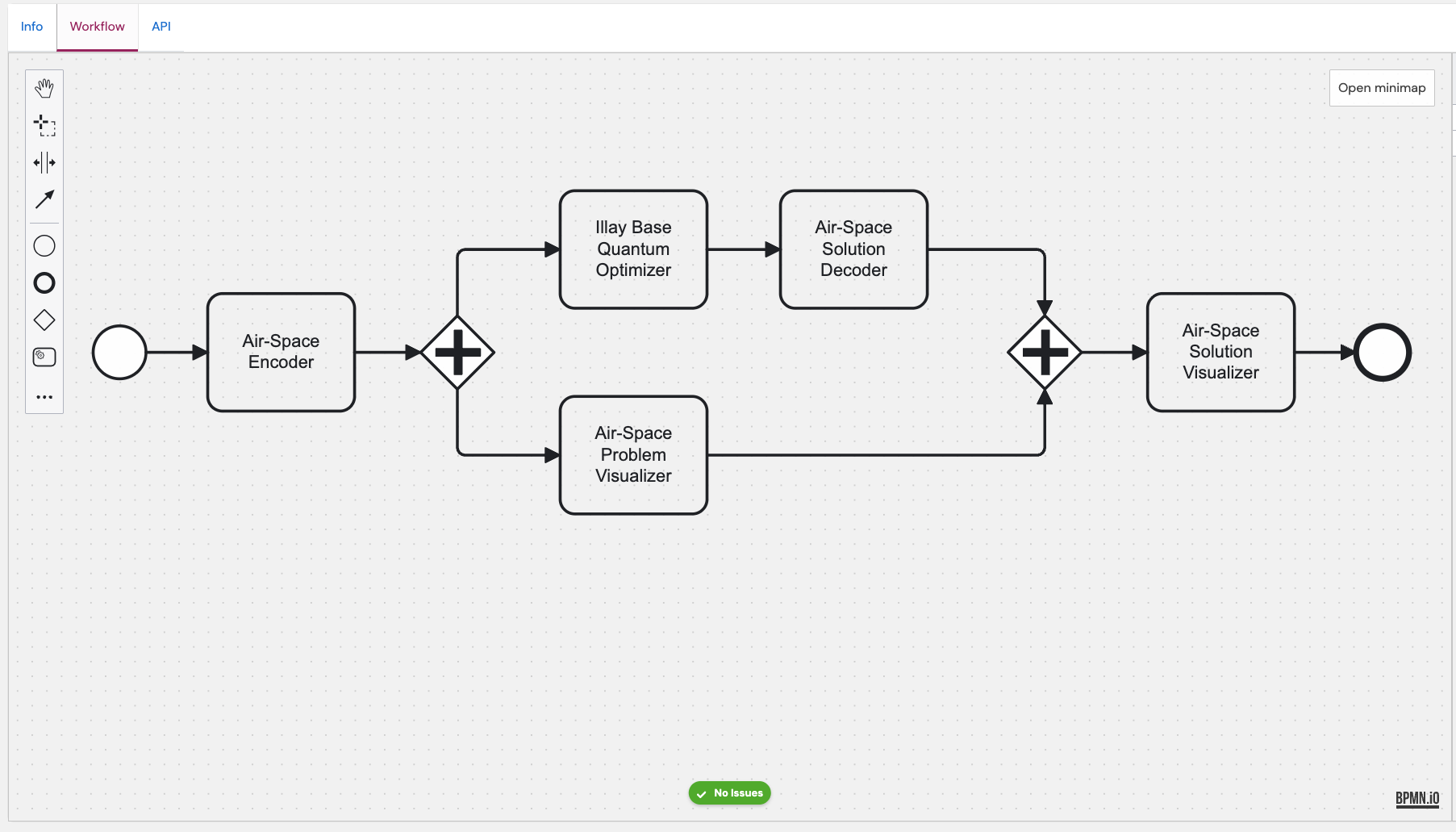
○ → [Encode Routes] → ◇+ → [Solve with Illay] → [Decode Solution] → ◇+ → [Visualize Solution] → ●
                       └ → [Visualize Problem] -------------------→ ┘
Services
1. AirSpace Encoder
The AirSpace Encoder service converts flight routes into a quantum optimization problem. It analyzes which routes intersect and creates a quantum problem where the goal is to minimize conflicts by assigning routes to different corridors.
Input
json
{
  "flight_routes": [
    {
      "origin": "HEL",
      "destination": "FCO"
    },
    {
      "origin": "BER",
      "destination": "MAD"
    }
  ]
}
Output
coefficients: Mathematical representation of the optimization problemairports: List of airports with coordinates (for visualization)route_mapping: Mapping between flight routes and quantum qubits
2. Illay Base Quantum Optimizer Service
The Kipu Illay Base Quantum Optimizer service solves a quantum optimization problem. In this case, the one encoded by the AirSpace Encoder. To achieve that, it executes a quantum algorithm to find the optimal corridor assignments that minimize conflicts.
Input
problem: The problem from the encoderproblem_type: "binary" (each route is assigned yes/no to each corridor)shots: Number of quantum circuit executions (higher = more accurate)num_greedy_passes: Optimization iterations
Output
result: Quantum solutionresult.mapped_solution: Best solution found
3. AirSpace Decoder
The AirSpace Decoder converts the quantum solution back to human-readable format.
Input
solution: The quantum result from Illayroutes: The quantum mapping from the encoder
Output
channels: List of corridors with their assigned routes.
For example:
json
[
  {
    "channel": "Corridor 0",
    "routes": [
      {
        "origin": "HEL",
        "destination": "FCO"
      }
    ]
  },
  {
    "channel": "Corridor 1",
    "routes": [
      {
        "origin": "CDG",
        "destination": "OTP"
      },
      {
        "origin": "FCO",
        "destination": "CDG"
      }
    ]
  }
]
4. Air Traffic Visualizer
The Air Traffic Visualizer creates visual maps of flight routes and corridor assignments.
Input
channels: Corridor assignments from decoder (or custom structure for problem visualization)airports: Airport coordinates from encoderfile_output_dir: Datapool location to store the imagefilename: Name for the generated visualization
Output
Saves an interactive map visualization to the specified datapool
Part 2: Creating the Workflow Service
Prerequisites
Before starting this tutorial, you should:
- Be familiar with basic quantum computing concepts
- Have a new application created for our new workflow service
- Name your application anything you prefer (e.g.,
air-traffic-demo). Consistent naming helps when selecting services later. - Have subscriptions to the following Kipu services within the application:
- Illay Base Quantum Optimizer You can create a free subscription to this service using our marketplace. Simply navigate to "Pricing & Subscription" and click "Subscribe". Subscribe to Illay within the same application you'll use for this workflow before opening the Workflow Modeler.
- Create three new services from our public implementation:
- Click each implementation link below:
- AirSpace Encoder - Converts flight routes to quantum problems
- AirSpace Decoder - Converts quantum solutions to corridor assignments
- Air Traffic Visualizer - Generates map visualizations
- Click "Create Service" first on the top right inside each implementation, then return here for the next steps
- Click each implementation link below:
- Publish internally: Open each service → Publish → **Internal **. You should see them on the top of your list of services.
- Subscribe to each AirSpace service within your application:
- Navigate to your application's subscriptions page
- Click "Subscribe Internally"
- In the dropdown, select each AirSpace service and click "Subscribe"
Important
Make sure to subscribe to all the services within an application. **Use Personal context ** for this tutorial; other contexts (e.g., "Kipu Quantum") may cause errors.
TIP
Use the same application for all services. You can subscribe to multiple services within one application as well as have subscriptions to the same service in different applications.
Naming Conventions Used in This Tutorial
Throughout this tutorial, we use consistent names for each workflow step. Here's a quick reference:
| Logical step | Standard name | Notes |
|---|---|---|
| Encoder service task | Encode Flight Routes | Converts flight routes to quantum problems |
| Illay optimizer task | Solve Quantum Problem | Executes quantum optimization |
| Decoder service task | Decode Quantum Solution | Converts quantum results to corridor assignments |
| Problem visualizer | Visualize Original Problem | Shows the input problem visualization |
| Solution visualizer | Visualize Optimized Solution | Shows the optimized solution visualization |
Need Help?
Join our Discord Server.
Step 1: Create the Workflow Service
Navigate to service creation
Select "Quantum Workflow Service"
Fill in the details:
Field Value Name Air Traffic Management Workflow Summary Quantum-optimized air corridor assignment for flight routes Description This workflow uses quantum computing to assign flight routes to air corridors, minimizing the risk of collisions when routes intersect. It encodes flight routes as a quantum optimization problem, solves it using Illay, and generates visual maps showing both the problem and solution. Click "Create Service"
Step 2: Open the Workflow Modeler
- Click on your newly created service
- Navigate to the "Workflow" tab
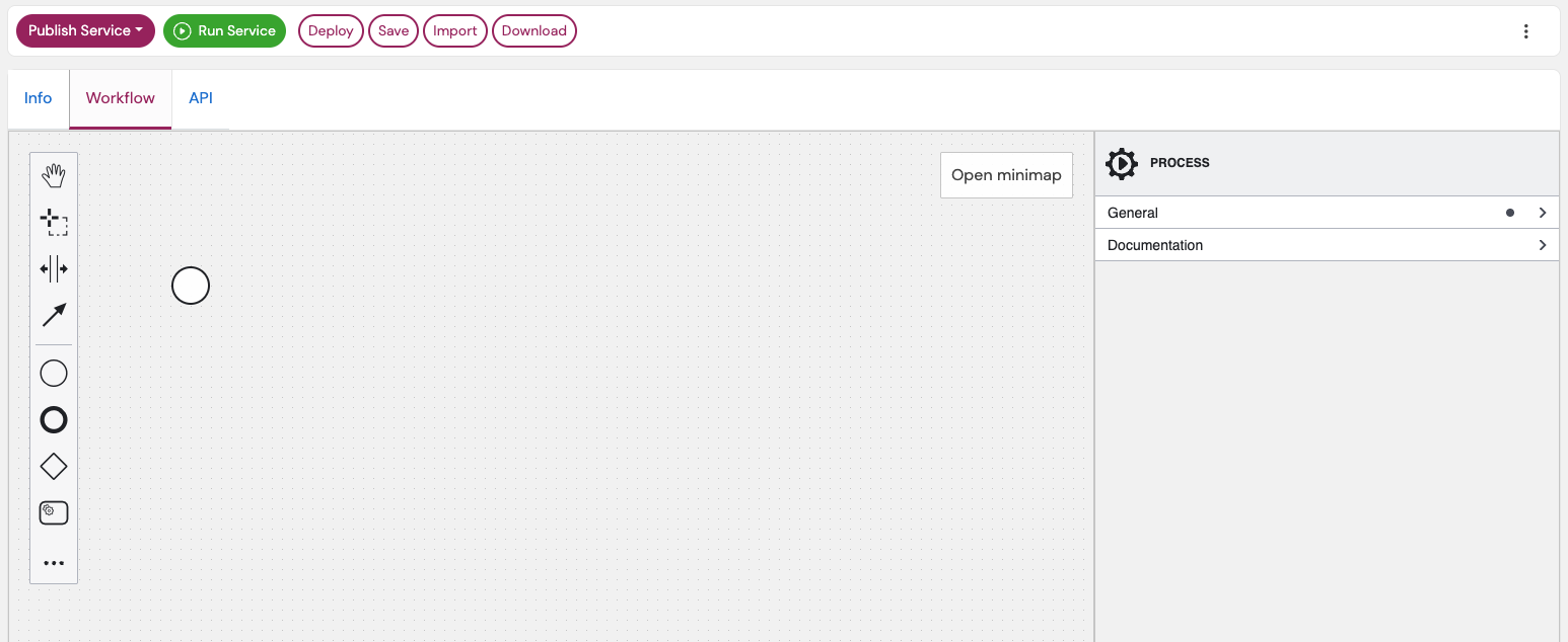
- You'll see the workflow modeler with a single Start Event (○)
Part 3: Building the Workflow Control Flow
WARNING
You can only use services in your workflow to which you have a valid subscription. Thus, if you developed a service yourself, you must publish it internally and add a subscription to it in an application. Similarly, for public services, you must have a valid subscription within an application.
We will model a workflow that should look something like this in the end:
Step 1: Define Workflow Input
First, configure what data your workflow will accept:
- Select the Start Event or create one (○)
- In the properties panel (right side), navigate to "API Description"
- Add this example request:
json
{
  "flightRoutes": [
    {
      "origin": "HEL",
      "destination": "FCO"
    },
    {
      "origin": "BER",
      "destination": "MAD"
    },
    {
      "origin": "CDG",
      "destination": "OTP"
    },
    {
      "origin": "FCO",
      "destination": "CDG"
    },
    {
      "origin": "OTP",
      "destination": "OSL"
    }
  ],
  "mapOutput": {
    "ref": "datapool",
    "id": "uuid-of-your-datapool"
  }
}
Understanding the Input
flightRoutes: Array of flight routes to optimize (use IATA airport codes)mapOutput: Datapool reference where visualization images will be savedref: Always "datapool" for platform datapoolsid: Your datapool UUID
Find your Datapool UUID: Navigate to Data → Datapools in the left navigation, open your datapool, and copy the **UUID ** from the details panel.
Step 2: Add the AirSpace Encoder
- Drag a Platform Service Task from the palette onto the canvas
- Connect the Start Event to this task (click Start Event, drag the arrow)
- Click the wrench icon (🔧) on the task
- Select the AirSpace Encoder service from the dropdown
- In the General tab (properties panel), set Name to:
Encode Flight Routes
Step 3: Create Parallel Gateway for Dual Visualization
After encoding, we want to:
- Solve the quantum problem AND
- Visualize the original problem
Both can happen in parallel:
- Drag a Gateway (◇) after the encoder task
- Click on the Gateway and make it a Parallel Gateway (◇+) by clicking on the wrench icon
- Connect the encoder task → parallel gateway
- This gateway will split the flow into two parallel paths
Step 4: Add Quantum Solving Branch (Top Path)
4.1: Add Illay Base Quantum Optimizer Service
- Drag a Platform Service Task above the parallel gateway
- Connect parallel gateway → this task
- Click wrench icon (🔧), select Illay Base Quantum Optimizer Service
- Set Name to:
Solve Quantum Problem
4.2: Add Decoder Service
- Drag another Platform Service Task after Illay
- Connect Illay task → this task
- Click wrench icon (🔧), select AirSpace Decoder
- Set Name to:
Decode Quantum Solution
Step 5: Add Problem Visualization Branch (Bottom Path)
- Drag a Platform Service Task below the parallel gateway
- Connect parallel gateway → this task (second branch)
- Click wrench icon (🔧), select Air Traffic Visualizer
- Set Name to:
Visualize Original Problem
Step 6: Add Synchronization Gateway
Both parallel branches must complete before continuing:
- Drag another Parallel Gateway to the right
- Connect the decoder task → this synchronization gateway
- Connect the problem visualizer task → this synchronization gateway
Gateway Default
When you drag a Gateway from the palette, the default is Exclusive. For this tutorial, switch it to **Parallel (◇+) ** by clicking the gateway and selecting the parallel type from the properties panel.
Step 7: Add Solution Visualization
- Drag a Platform Service Task after the synchronization gateway
- Connect synchronization gateway → this task
- Click wrench icon (🔧), select Air Traffic Visualizer
- Set Name to:
Visualize Optimized Solution
Step 8: Add End Event
- Drag an End Event (●) from the palette
- Connect the solution visualizer → end event
- Save your workflow (button in top left)
Verify Your Control Flow
Your workflow should now look like this:
○ → [Encode Flight Routes] → ◇+ → [Solve Quantum Problem] → [Decode Quantum Solution] → ◇+ → [Visualize Optimized Solution] → ●
                             └ -→ [Visualize Original Problem] -----------------------→ ┘
Your workflow should look similar to the image above.
TIP
Make sure to have the green "No issues" indicator at the bottom of the modeler. If it is grey, simply click on it to activate the model errors.
If there are any issues, you will see a red indicators at the corresponding elements.
Publishing Note
You do not need to publish the newly created **Workflow Service ** itself for this tutorial. Deploying the workflow (covered in Part 5) is sufficient for testing.
Part 4: Configuring Data Flow
Now that the control flow is complete, configure how data moves between services.
Step 1: Configure AirSpace Encoder
Select the "Encode Flight Routes" platform service task.
Inputs Section:
Click + to add input mapping:
| Local variable name | Variable assignment value | Description |
|---|---|---|
flight_routes | flightRoutes | Array of flight routes from workflow input |
Why no quotes?
flightRoutes (without quotes) references the workflow variable from the Start Event. This directly passes the flight routes array to the encoder service.
Outputs Section:
Store the encoder's three outputs as workflow variables.
Order Matters
In the UI, Process variable appears first and Assignment/Result second. Follow this order for all output mappings.
Click + for each output mapping:
| Process variable name | Result variable name | Description |
|---|---|---|
coefficients | quantumProblem | Mathematical representation of the optimization problem |
airports | airportsInRoutes | List of airports with coordinates for visualization |
route_mapping | quantumMapping | Mapping between flight routes and quantum qubits |
Step 2: Configure Illay Base Quantum Optimizer Service
Select the "Solve Quantum Problem" platform service task.
Inputs Section:
Click + for each input mapping:
| Local variable name | Variable assignment value | Description |
|---|---|---|
problem | quantumProblem | The encoded quantum optimization problem from the encoder |
problem_type | "binary" | Type of optimization problem (quoted literal string) |
shots | 1000 | Number of quantum circuit executions for accuracy |
num_greedy_passes | 0 | Number of classical optimization iterations |
Using Literal Values
When using literal strings or numbers:
- Strings: Use quotes:
"binary" - Numbers: No quotes:
1000 - Booleans: No quotes:
trueorfalse
Outputs Section:
Click + to add output mapping:
| Process variable name | Result variable name | Description |
|---|---|---|
result.mapped_solution | quantumSolution | Best quantum solution found by the optimizer |
Step 3: Configure AirSpace Decoder
Select the "Decode Quantum Solution" platform service task.
Inputs Section:
Click + for each input mapping:
| Local variable name | Variable assignment value | Description |
|---|---|---|
solution | quantumSolution | The quantum solution from Illay optimizer |
routes | quantumMapping.routes | Route mapping from the encoder (using dot notation) |
Accessing Nested Data
quantumMapping.routes uses dot notation to access the routes property within the quantumMapping object. This is standard FEEL expression syntax.
Outputs Section:
Click + to add output mapping:
| Process variable name | Result variable name | Description |
|---|---|---|
channels | solutionChannels | Decoded corridor assignments with routes per corridor |
Step 4: Configure Problem Visualizer
Select the "Visualize Original Problem" platform service task.
Inputs Section:
Click + for each input mapping:
| Local variable name | Variable assignment value | Description |
|---|---|---|
channels | [{"channel": "Problem", "routes": flightRoutes}] | Single channel containing all original routes (JSON array) |
airports | airportsInRoutes | Airport coordinates from encoder |
file_output_dir | {"id": mapOutput.id, "ref": "datapool"} | Datapool reference for saving the visualization |
filename | "problem-visualization" | Name for the generated problem map image |
Understanding the channels Input
The visualizer expects an array of channel objects. For the problem visualization, we create a single channel called "Problem" containing all the original routes:
json
[
  {
    "channel": "Problem",
    "routes": flightRoutes
  }
]
This shows all routes in one color before optimization, helping visualize which routes intersect.
Step 5: Configure Solution Visualizer
Select the "Visualize Optimized Solution" platform service task.
Inputs Section:
Click + for each input mapping:
| Local variable name | Variable assignment value | Description |
|---|---|---|
channels | solutionChannels | Decoded corridor assignments from the decoder |
airports | airportsInRoutes | Airport coordinates from encoder (same as problem visualizer) |
file_output_dir | {"id": mapOutput.id, "ref": "datapool"} | Datapool reference for saving the visualization |
filename | "solution-visualization" | Name for the generated solution map image |
Channel Difference
Notice the solution visualizer uses solutionChannels from the decoder, which contains multiple corridors (Corridor 0, Corridor 1, etc.) with optimized route assignments. Each corridor is displayed in a different color, showing the conflict-free solution.
Save Your Work
Click the Save button in the top left of the modeler.
Part 5: Testing Your Workflow
Step 0: Define the input schema
Before executing the workflow, define the input schema for better validation and usability.
Learn More
For a comprehensive explanation of how workflow services automatically generate their API from input schemas, see Automatic API Generation.
- Select the Start Event (○)
- In the properties panel, navigate to the "API Description" section
- Paste the following JSON schema in the
Request Schemafield:json{ "type": "object", "properties": { "flightRoutes": { "type": "array", "items": { "type": "object", "properties": { "origin": { "type": "string" }, "destination": { "type": "string" } }, "required": ["origin", "destination"] } }, "mapOutput": { "type": "object", "properties": { "id": { "type": "string", "format": "uuid" }, "ref": { "type": "string", "enum": [ "datapool" ] } }, "required": ["id", "ref"], "additionalProperties": false } }, "required": ["flightRoutes", "mapOutput"] }
Based on this schema, the platform will validate your input when executing the workflow via the Service Jobs page.
Step 1: Deploy the Workflow
- In your workflow service, navigate to the "Workflow" tab
- Click "Deploy" in the top left
- Wait for deployment to complete (green toast will appear in the top right)
Save → Deploy
After any change in the modeler, click Save. However, your changes will only be available in an execution, if you deployed the workflow. To deploy it, simply click on Deploy before running again. Deploy also saves the latest changes.
Step 2: Prepare Your Datapool
- Navigate to Datapools (or use Left nav: Data → Datapools if the link fails)
- Create a new datapool (or use an existing one). Name your datapool freely (e.g.,
air-traffic-results-01). - Copy the datapool UUID from the datapool details page
Step 3: Execute the Workflow
On your workflow service page, click the green "Run Service" button in the top left
TIP
As an alternative, you can navigate to the Service Jobs page and click on "Create Service Job". In the service dropdown, select your workflow service.
Input Mode: Use Manual JSON and paste the sample below. Replace the datapool UUID.
In the "Input Mode" section, use this test request (⚠️ Do not forget to replace the datapool ID):
json{ "flightRoutes": [ { "origin": "HEL", "destination": "FCO" }, { "origin": "BER", "destination": "MAD" }, { "origin": "CDG", "destination": "OTP" }, { "origin": "FCO", "destination": "CDG" }, { "origin": "OTP", "destination": "OSL" } ], "mapOutput": { "ref": "datapool", "id": "YOUR-DATAPOOL-UUID-HERE" } }Replace
YOUR-DATAPOOL-UUID-HEREwith your actual datapool UUIDClick "Create Job"
You'll automatically be redirected to the job details page
Step 4: Monitor Execution
Where to find Service Jobs: Navigate to Left nav: Operations → Service Jobs.
- Navigate to the "Service Jobs" tab
- Find your job in the list (most recent will be at the top)
- Click on the job to see detailed execution progress
- Watch as each service task completes:
- ✅ Encode Flight Routes
- 🔄 Solve Quantum Problem (this may take 1-2 minutes)
- 🔄 Visualize Original Problem
- ✅ Decode Quantum Solution
- ✅ Visualize Optimized Solution
Parallel Execution in Action
Notice that "Solve Quantum Problem" and "Visualize Original Problem" run simultaneously. This is parallel processing working as designed!
Troubleshooting
If your workflow fails, check these common issues:
- Re-check Part 4 output mappings (Process variable → Result variable order)
- Confirm Parallel vs Exclusive gateway where indicated
- Ensure Personal context (not "Kipu Quantum")
- Save → Deploy again, then re-run
- If the encoder fails, start with output mapping fixes
Step 5: View Results
When the workflow completes, navigate to your datapool
You should see two new files:
problem-visualization.png- Shows all original routessolution-visualization.png- Shows routes organized into optimal corridors
If files don't appear immediately, refresh the datapool tab.
Preview and compare the images:
- Problem visualization: All routes shown together (potential conflicts)
- Solution visualization: Routes colored by corridor assignment (conflict-free)
Part 6: Understanding the Results
Reading the Visualizations
Problem Visualization
- All flight routes shown in the same color
- You can see where routes intersect (potential collision points)
- This represents the input to the optimization problem
Solution Visualization
- Routes colored by corridor assignment
- Different colors = different corridors (vertically separated in real airspace)
- Routes in the same corridor don't intersect
- This represents the optimized solution from quantum computing
What the Quantum Computer Did
The Illay Base Quantum Optimizer service:
- Explored many possible corridor assignments
- Used quantum superposition to evaluate multiple solutions simultaneously
- Found the assignment that minimizes conflicts
- Returned the optimal solution
Part 7: Returning Data from Workflows
By default, your air traffic workflow saves visualization images to the datapool but doesn't return data via the API to external callers. To return corridor assignments and other results programmatically, configure output variables on the End Event:
- Select the End Event (●) in your workflow
- Navigate to the "Outputs" section in the properties panel
- Add output variables using FEEL expressions
The output variables become fields in your workflow's API response. For example, if you configure:
- Variable name:
corridorswith expression:solutionChannels - Variable name:
quantum_resultwith expression:quantumSolution - Variable name:
statuswith expression:"optimization_complete"
Your API will return:
json
{
  "corridors": [
    {
      "channel": "Corridor 0",
      "routes": [
        {
          "origin": "HEL",
          "destination": "FCO"
        }
      ]
    },
    {
      "channel": "Corridor 1",
      "routes": [
        {
          "origin": "BER",
          "destination": "MAD"
        }
      ]
    }
  ],
  "quantum_result": [
    1,
    0,
    1,
    0,
    1
  ],
  "status": "optimization_complete"
}
This enables external applications to consume the optimization results programmatically, in addition to the visual maps stored in your datapool.
Part 8: Next Steps
Extend the Workflow
Now that you have a working air traffic management workflow, try these extensions:
Multi-Objective Optimization: Add fuel efficiency and delay minimization to the optimization goals
Dynamic Route Updates: Create a loop that re-optimizes when new flights are added
Weather Integration: Add a weather service that influences corridor assignments
Real-Time Monitoring: Connect to a live flight data API for real-world testing
Comparative Analysis: Run the same problem on multiple quantum backends and compare results
Share Your Workflow
- Add comprehensive documentation to your service description
- Publish the workflow service to the Platform marketplace
- Create example API calls in the service documentation
- Share your results with the Platform community
Learn More
- FEEL Expressions Reference: Advanced data transformations
- BPMN 2.0 Specification: Complete BPMN reference
- Platform API Documentation: Integrate workflows into your applications
Summary
Congratulations! You've built a production-ready quantum workflow that:
- ✅ Solves a real-world optimization problem
- ✅ Uses quantum computing (Illay) for enhanced performance
- ✅ Implements parallel processing for efficiency
- ✅ Generates visual results for easy interpretation
- ✅ Handles data flow between multiple services
Key Takeaways
- Service Orchestration: Workflows coordinate multiple services without custom code
- Parallel Processing: Use parallel gateways to execute independent tasks simultaneously
- Data Flow: Map inputs/outputs carefully using FEEL expressions
- Quantum Integration: Illay makes quantum computing accessible through simple APIs
- Visualization: Transform complex results into understandable visual formats
What You Learned
- Creating complex workflow control flows with parallel branches
- Configuring service task inputs/outputs with nested data structures
- Integrating quantum optimization services
- Testing and debugging workflows
- Best practices for production deployment
Appendix: Quick Reference
BPMN Elements Cheat Sheet
| Element | Symbol | Purpose | When to Use |
|---|---|---|---|
| Start Event | ○ | Workflow entry point | Every workflow needs exactly one |
| End Event | ● | Workflow completion | Mark successful completion |
| Platform Service Task | ▢ | Execute a service | Call any subscribed Platform service |
| Parallel Gateway | ◇+ | Split/merge parallel flows | Run tasks simultaneously |
| Exclusive Gateway | ◇× | Conditional branching | Choose one path based on condition |
| Sequence Flow | → | Execution order | Connect all elements |
| Error Boundary Event | ⚡ on task border | Handle errors | Catch service failures |
| Timer Boundary Event | ⏰ on task border | Handle timeouts | Prevent hanging tasks |
Data Mapping Quick Reference
Input Configuration
Local variable name: data
Variable assignment value: {
  "field1": workflowVariable,
  "field2": "literal value"
}
Output Configuration
Result variable name: outputVariable
Process variable name: response.field
FEEL Expression Examples
javascript
// Variables (no quotes)
variableName
object.property

// Literals (with quotes for strings)
"string value"
123
true

// Arrays and objects
  [1, 2, 3]
{
  "key"
:
  value
}

// Operations
value1 + value2
count(array)
string(number)

// Conditions
value > 10
count(routes) < 5
Resources
Documentation:
Services:
Community:
Join our Discord Server.